
Location selection depends on the application, such as urban background monitoring, traffic monitoring, etc. The user should consider the following when selecting the final location:
- Install the unit far away from pollution sources that are very close and have insufficient air flow (such as chimneys, air conditioners, etc.) that may disrupt your readings.
- Install the unit between 3 and 4 meters high.
- For optimal sensor performance, it is recommended to mount the unit in a location that is not directly exposed to sunlight or receives as little sunlight as possible.
To ensure proper operation and due to design, Sensorbee Modbus products must be installed with the air inlet of the sensors facing downward. Different types of installations are possible, such as vertical masts or on walls.
Connecting the external cables to the unit before clicking it onto the bracket may be easier.
9.1 Installation to Mast
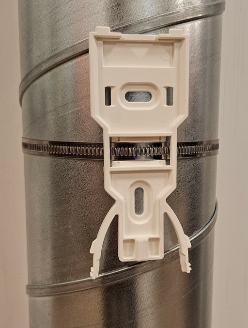
As figure 1 shows, the mounting bracket is attached to the mast using a stainless steel hose clamp. Then, click the unit onto the bracket.
9.2 Installation on Wall
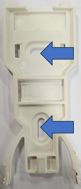
Attach the mounting bracket to the wall using two screws, as shown in figure 2. Then, click the unit onto the bracket.
9.3 Power and RS-485
To connect power and the RS-485 bus, follow these steps.
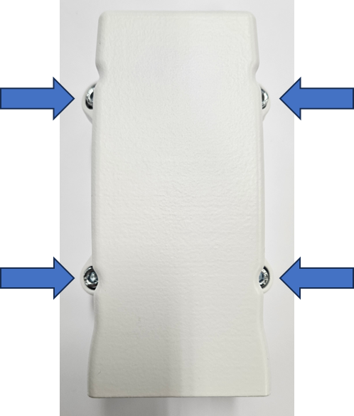
Use an PH2 Phillips screwdriver to unscrew the sensor-house from the base as shown in figure 3.
The incoming power and RS-485 bus are interfaced via the J400 terminal block. This is achieved by depressing the orange pin, inserting the stripped wire into the terminal block, and subsequently releasing the orange pin.
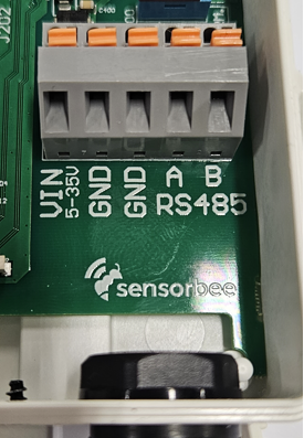
Pin | Function |
1 | 5-35VDC Input |
2 | GND (0V) |
3 | GND (0V) |
4 | RS-485-A |
5 | RS-485-B |
9.3 Termination
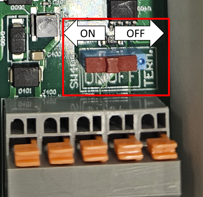
A 120-ohm resistor can be connected to the RS-485 bus using SW400.
Markings on the circuit board indicate the on and off positions.
Whether or not to connect the 120-ohm resistor depends on the specific bus configuration that the unit will be connected to.
Once the cable installation is complete and the termination has been determined, assemble the unit. Use an PH2 Phillips screwdriver to screw the sensor-house back the base as shown in figure 6.
Double check that the cable between the sensor-house and base does not get squeezed in the seal between them.

Upon powering on, the status LED (5) will cycle through various colors to indicate its current status. Refer to the LED Status section for explanations