The temperature sensor gauges the ambient temperature in its environment.
In the Sensorbee Pro series, which includes both the Air Pro and Modbus Pro, the temperature sensor is situated within the front-end module (SB3516). This digital sensor operates with high precision across a wide temperature range. Making use of a bandgap temperature reference and an analog-to-digital converter (ADC), it accurately captures and conveys temperature data, ensuring reliable monitoring.
For comprehensive sensor specifications and performance metrics, kindly consult the SB3516 datasheet.
In the Sensorbee Lite series, encompassing both the Air Lite and Modbus Lite, the temperature sensor is integrated directly within an associated sensor dome, designated as SB3380. This digital sensor operates with high precision across an expansive temperature spectrum. Leveraging a bandgap temperature reference combined with an analog-to-digital converter (ADC), it captures and communicates temperature data with exceptional accuracy, ensuring precise monitoring.
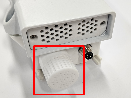
For comprehensive specifications and performance details of the sensor, consult the SB3380 datasheet.
Installation
If the unit is connected to an external power source, such as a power supply or solar panel, ensure to turn off the power. For Air Pro units, the status LED will illuminate red for 10 seconds and then turn off, signaling it's safe to proceed. For Modbus units, disconnect the incoming power from the terminal block to ensure the power is completely off.
Pro Series
Please refer to the particle sensor's documentation for installation instructions.
Lite Series
This procedure is advanced and it is recommended to be conducted in a controlled environment with access to proper equipment.
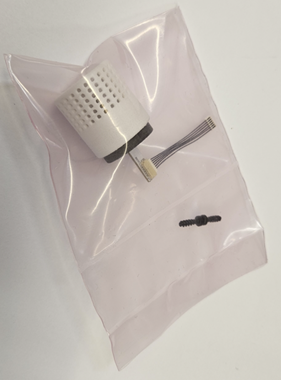
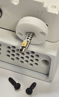
The Temperature Sensor Kit (SB3380) is provided with the following components:
- Two screws
- One sensor mesh
- One sensor mounted on a plate
- One fine pitch cable.
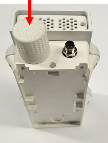
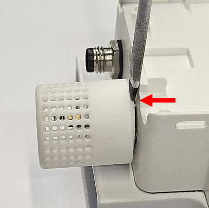
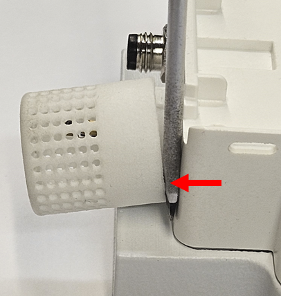
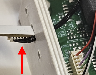
Utilize a small flathead screwdriver to remove the mesh guard shielding the internal sensors.
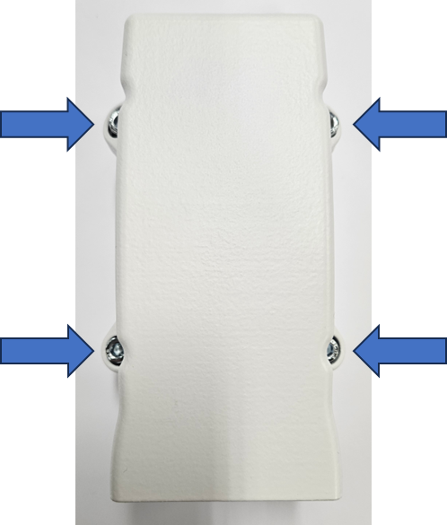
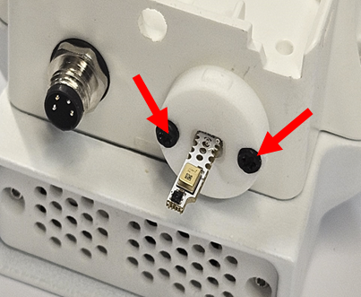
Use a T6 Torx screwdriver to unscrew the two screws securing the sensor and its mounting plate.

Use an PH2 Phillips screwdriver to unscrew the sensor-house from the base as shown in figure 8.
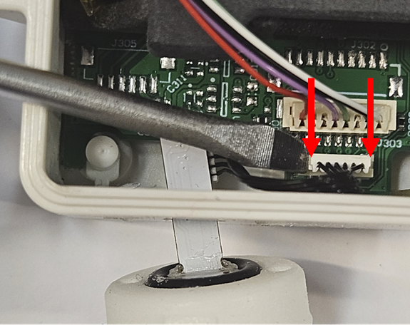
Place the sensor-house upside down next to the base, without disconnecting the cable between them. Use a small flathead screwdriver or tweezers to gently disconnect the sensor cable connector from the connector on the PCB.
Sensorbee Air Lite:
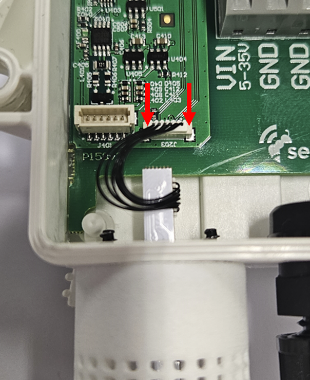
Sensorbee Modbus Lite:
Remove the sensor and cable by angling the cable at the connector point and gently pulling it through the hole in the base cover.
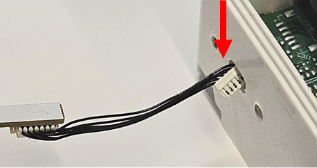
Insert the new sensor by angling the cable. Exercise extreme caution to ensure the cables are not damaged when threading them through the small hole in the base cover
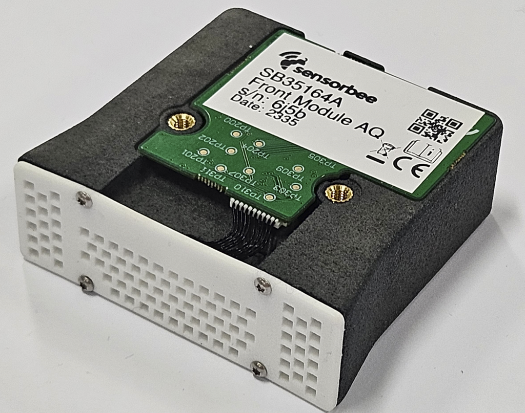
Fasten the two screws to secure the sensor and its mounting plate. Ensure the plate sits flush against the base cover. Also, ensure the components on the sensor board point downwards, away from the particle sensor, as depicted in figure 13.
It might be beneficial to use a microscope or magnifying glass to ensure the connector is properly seated and to check for any damaged wires.
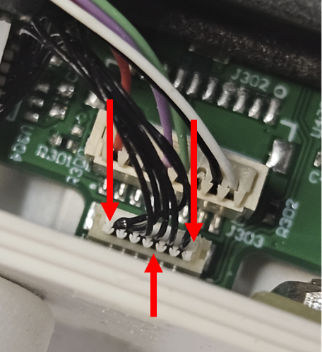
Ensure the cable is oriented as shown in figure 14, with the cable in the connector pointing towards the base cover. Exercise extreme caution when pressing the cable connector into the connector on the PCB. Use a small flathead screwdriver or tweezers, focusing on the edges, and take care not to damage any fine wires. The cable connector should be almost flush in height with the connector on the PCB. Figure 14 shows an Sensorbee Air Lite, but the princip is the same on the Sensobee Modbus Lite.
Use a PH2 Phillips screwdriver to fasten the sensor-house to the base as shown in figure 15.

Place the device on its edge and secure the sensor mesh cover by pressing it all around the edges until it sits snugly. It might feel quite tight before the cover locks into place.